


As this document is under construction, you may expect some level of errors and sentences that stop without
If you see anything that is clearly wrong, or poorly explained (if you find it hard to understand from the article then it's poorly explained) then please don't hesitate to contact me about it. ([email protected])
Lighting and shadow casting algorithms can be very roughly divided into two categories; Direct Illumination and Global Illumination. Many people will be familiar with the former category, and the problems associated with it. This article will briefly discuss the two approaches, then give an in-depth study of one Global Illumination method, Radiosity.
There are all sorts of techniques under this heading: Shadow Volumes, Z-Buffer methods, Ray Tracing . . . But as a general rule, they all suffer from similar problems, and all require some kind of fudge in order to overcome them.
|
|
|
|
It it quite common for people to claim that ray tracers and other renderers produce 'photo-realistic' results. But imagine someone were to show you a typical ray traced image, and claim it was a photo. It would not be long before you were claiming in return that they were blind or lying.
It should also be noted that, in the real world, it is still possible to see objects that are not directly lit; shadows are never completely black. Direct Illumination renderers try to handle such situations by adding an Ambient Light term. Thus all objects receive a minimum amount of uni-directional light.
|
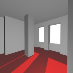
Lighting a simple scene with Direct LightingI modeled this simple scene in 3D Studio. I wanted the room to look as if it was lit by the sun shining in through the window. So, I set up a spotlight to shine in. When I rendered
it, the entire room was pitch black, except for a couple of patches on the
floor that the light reached. |
 |
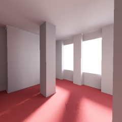
Lighting a simple scene with Global LightingI modeled the same scene in my own radiosity renderer. To provide the source of light, I rendered an image of the sky with Terragen, and placed it outside the window. No other source of light was used.With no further effort on my part, the room looks realistically
lit.
|
 |
I would now like to ask an expert on shadows, who will explain to you everything they know about the subject. My expert is a tiny patch of paint on the wall in front of me.
In my next article, I will be explaining how you can make your own talking paint.
So, the basic principal behind the radiosity renderer is to remove the
distinction between objects and light sources. Now, you can consider everything
to be a potential light source.
Anything that is visible is either emitting
or reflecting light, i.e. it is a source of light. A Light Source. Everything
you can see around you is a light source. And so, when we are considering how
much light is reaching any part of a scene, we must take care to add up light
from all possible light sources.
 |
A Simple SceneWe begin with a simple scene: a room with three windows. There are a couple of pillars and some alcoves, to provide interesting shadows.It will be lit by the scenery outside the windows, which I will assume is completely dark, except for a small, bright sun. |
 |
Now, lets choose one of the surfaces in the room, and consider the lighting on it. |
 |
As with many difficult problems in computer
graphics, we'll divide it up into little patches (of paint), and try to
see the world from their point of view.
From now on I'll refer to these patches of paint simply as patches. |
 |
Take one of those patches. And imagine you are that patch. What does the world look like from that perspective? |
 |
View from a patchPlacing my eye very carefully on the patch, and looking outwards, I can see what it sees. The room is very dark, because no light has entered yet. But I have drawn in the edges for your benefit.By adding together all the light it sees, we can calculate the total amount of light from the scene reaching the patch. I'll refer to this as the total incident light from now on. This patch can only see the room and the darkness outside. Adding up the incident light, we would see that no light is arriving here. This patch is darkly lit. |
 |
View from a lower patchPick a patch a little further down the pillar. This patch can see the bright sun outside the window. This time, adding up the incident light will show that a lot of light is arriving here. This patch is brightly lit. |
 |
Lighting on the PillarHaving repeated this process for all the patches, and added up the incident light each time, we can look back at the pillar and see what the lighting is like.The patches nearer the top of the pillar, which would not see the sun, are in shadow, and those that can are brightly lit. Those that could see the sun partly obscured by the edge of the window are only dimly lit. And so Radiosity proceeds in much the same fashion. As you have seen, shadows naturally appear in parts of the scene that cannot see a source of light. |
 |
Entire Room Lit: 1st PassRepeating the process for every patch in the room, gives us this scene. Everything is completely dark, except for surfaces that have received light from the sun.So, this doesn't look like a very well lit scene. Ignore the fact that the lighting looks blocky; we can fix that by using many more patches. What's important to notice is that the room is completely dark, except for those areas that can see the sun. At the moment it's no improvement over any other renderer. Well, it doesn't end here. Now that some parts of the room are brightly lit, they have become sources of light themselves, and could well cast light onto other parts of the scene. |
 |
View from the patch after 1st PassPatches that could not see the sun, and so received no light, can now see the light shining on other surfaces. So in the next pass, this patch will come out slightly lighter than the completely black it is now. |
 |
Entire Room Lit: 2nd PassThis time, when you calculate the incident light on each patch in the scene, many patches that were black before are now lit. The room is beginning to take on a more realistic appearance.What's happened is that sun light has reflected once from the floor and walls, onto other surfaces. |
 |
Entire Room Lit: 3rd PassThe third pass produces the effect of light having reflected twice in the scene. Everything looks pretty much the same, but is slightly brighter.The next pass only looks a little brighter than the last, and even the 16 th is not a lot different. There's not much point in doing any more passes after that. The radiosity process slowly converges on a solution. Each pass is a little less different than the last, until eventually it becomes stable. Depending on the complexity of the scene, and the lightness of the surfaces, it may take a few, or a few thousand passes. It's really up to you when to stop it, and call it done. |
 |
 |
| 4th Pass | 16th Pass |
Emmision
Though I have said that we'll
consider lightsources and objects to be basically the same, there must obviously
be some source of light in the scene. In the real world, some objects do emit
light, and some don't, and all objects absorb light to some extent. We must
somehow distinguish between parts of the scene that emit light, and parts that
don't. We shall handle this in radiosity by saying that all patches emit light,
but for most patches, their light emmision is zero. This property of a patch,
I'll call emmision.
Reflectance
When light hits a surface, some
light is absorbed and becomes heat, (we can ignore this) and the rest is
reflected. I'll call the proportion of light reflected by a patch
reflectance.
Incident and Excident Light
During each pass,
it will be necessary to remember two other things, how much light is arriving at
each patch, and how much light is leaving each patch. I'll call these two,
incident light and excident light. The excident light is the
visible property of a patch. When we look at a patch, it is the excident light
that we're seeing.
    incident light = sum of all light that a patch can see

    excident light = (incident light*reflectance) + emmision
Patch structure
Now that we know all the
necessary properties of a patch, it's time to define a patch. Later, I'll
explain the details of the four variables.
  structure PATCH

    emmision

    reflectance

    incident

    excident

  end structure
Now that I've explained the basics of the algorithm, I'll tell it again in pseudocode form, to make it concrete. Clearly this is still quite high level, but I'll explain in more detail later.
|
Explanation of Code initialise patches: Passes Loop: each patch collects light from the
scene calculate excident light from each
patch:
This process must be repeated many times to get a good effect. If the renderer needs another pass, then we jump back to Passes_Loop. |
 |
The Hemisphere Imagine a fish eye view wrapped onto a hemisphere. Place the hemisphere over a patch (left: red square), and from that patch's point of view, the scene wrapped on the inside of the hemisphere looks just like the scene from it's point of view. There's no difference. Placing a camera in the middle of the hemisphere, you can see that the view looks just like any other rendering of the scene (right). If you could find a way to render a fisheye view easily, then you could just sum up the brightness of every pixel to calculate the total incident light on the patch. However, it's not easy to render a fisheye view, and so some other way must be found to calculate the incident light. |
 Rendering from the centre of the hemisphere |
 |
The
Hemicube Surprisingly (or unsurprisingly, depending on how mathematical you are) a hemicube looks exactly the same as a hemisphere from the patch's point of view. |
 Rendering from the centre of the hemicube |
So, you can easily produce each of these images by placing a camera on a patch, and render it pointing forwards, up, down, left and right. The four side images are, of course, cut in half, and so, only half a rendering is required there.
 |
This is view of 3 spheres, rendered with a FOV of 90°. All
three spheres are the same distance from the camera, but because of the
properties of perspective transformation, objects at the edge of the image
appear spretched and larger than ones in the middle.
If this was the middle image of a hemicube, and the three spheres were light sources, then those near the edge would cast more light onto the patch than they should. This would be inaccurate, and so we must compensate for this. If you were to use a hemicube to calculate the total incident light falling on a patch, and just added together the values of all the pixel rendered in the hemicube, you would be giving an unfair weight to objects lying at the corners of the hemicube. They would appear to cast more light onto the patch. To compensate for this, it is necessary to 'dim' the pixels at the edges and corners, so that all objects contribute equally to the incident light, no matter where they may lie in the hemicube. Rather than give a full explanation, I'm just going to tell you how this is done. |
 |
Pixels on a surface of the hemicube are multiplied by the cosine of
the angle between the direction the camera is facing in, and the line from
the camera to the pixel.
On the left is an image of the map used to compensate for the distortion. (shown half size relative to the image above) |
 |
Any budding graphics programmer knows Lambert's cosine law:
The apparent brightness of a surface is proportional to the cosine of the
angle between the surface normal, and the direction of the light.
Therefore, we should be sure to apply the same law here. This is simply
done by multiplying pixels on the hemicube by the relevant amount.
On the left is an image of the map used to apply Lambert's law to the hemicube. White represents the value 1.0, and black represents the value 0.0. (shown half size relative to the image above) |
First, it renders the 5 faces of the hemicube using the procedure RenderView(point, vector, part). This procedure takes as it's arguments a point, telling it where the camera should be for the rendering, a vector, telling it what direction the camera should be pointing in, and another argument telling it which part of the final image should be rendered. These 5 images are stored in hemicube structure called H (left column of images below).
Once the hemicube H has been rendered, it is multiplied by the multiplier hemicube M (middle column of images below), and the result is stored in the hemicube R (right column of images below).
Then the total value of the light in R is added up and divided by the number of pixels in a hemicube. This should give the total amount of light arriving at the point in question.
|
|
  structure light

    float Red

    float Green

    float Blue

  end structure
hemicube: used for storing the view of a scene from the point of view of some point in the scene. A Hemicube would consist of five images, as illustrated above, where each pixel was of type light. In the case of the Multiplier Hemicube, what is stored is not a value of light, but some multiplier value less than 1.0, as illustrated above.
  structure hemicube

    image front

    image up

    image down

    image left

    image right

  end structure
camera: for example structure camera
point lens
vector direction
end structure
Fortunately, this is something people have been doing since the dawn of time. Um, since the dawn of the raster display, and since then there has been much work put into rendering texture mapped scenes as fast as possible. I won't go into a whole lot of detail here, I'm really not the person best qualified to be talking about optimised rendering. My own renderer is so slow you have to use cussing words to describe it. The algorithm also lends itself well to optimisation with standard 3D graphics hardware, though you have do some fiddling and chopping to get it to render (3x32) bit textures.
The speed improvement I'm going to discuss in this article does not concern optimising the actual rendering of the hemicubes, but rather reducing the number of hemicubes that need to be rendered. You will, of course, have noticed that the light maps illustrated in the black and white renderings above were somewhat blocky, low resolution. Don't fear, their resolution can be increased as far as you want.
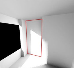 |
Take a look at the surface on the left, outlined in red.
The lighting is basically very simple, there's a bright bit, and a less
bright bit, with a fairly sharp edge between the two. To reproduce the
edge sharply, you would normally need a high resolution light map and,
therefore, have to render very many hemicubes. But it hardly seems
worthwhile rendering so many hemicubes just to fill in the bright or
less-bright areas which are little more than solid colour. It would be
more worthwhile to render a lot of hemicubes near the sharp edge, and just
a few in the other areas.
Well, it is possible, and quite straightforward. The algorithm I will describe below will render a few hemicubes scattered across the surface, then render more near the edges, and use linear interpolation to fill in the rest of the light map. |
| The Algorithm: On the far left you can see the light map in the
process of being generated. Next to it, you can see which pixels were
produced using a hemicube (red) and which were linearly interpolated
(green).
| ||
 |
1: Use a hemicube to
calculate every 4th pixel.
I'll show these pixels on the right as |
 |
 |
2: Pass Type 1:
Examine the pixels  which are
horizontally or vertically halfway between previously calculated pixels which are
horizontally or vertically halfway between previously calculated pixels
 . If the
neighbouring pixels differ by more than some threshold amount, then
calculate this pixel using a hemicube, otherwise, interpolate from the
neighbouring pixels. . If the
neighbouring pixels differ by more than some threshold amount, then
calculate this pixel using a hemicube, otherwise, interpolate from the
neighbouring pixels. |
 |
 |
3: Pass Type 2:
Examine the pixels  which are in the
middle of a group of 4 pixels. If the
neighbours differ by much, then use a hemicube for this pixel, otherwise
use linear interpolation. which are in the
middle of a group of 4 pixels. If the
neighbours differ by much, then use a hemicube for this pixel, otherwise
use linear interpolation. |
 |
 |
4: Pass Type 1: Same as step 2. |  |
 |
5: Pass Type 2: Same as step 3. | 
|
You should be able to see, from the maps on the left, that most of the light map was produced using linear interpolation. In fact, from a total of 1769 pixels, only 563 were calculated by hemicube, and 1206 by linear interpolation. Now, since rendering a hemicube takes a very long time indeed, compared to the negligable time required to do a linear interpolation, it represents a speed improvement of about 60% !
Now, this method is not perfect, and it can occasionally miss very small details in a light map, but it's pretty good in most situations. There's a simple way to help it catch small details, but I'll leave that up to your own imagination.
####  CODE EDITING IN PROGRESS - BIT MESSY STILL ####


 float ratio2(float a, float b)

 {

     if ((a==0) && (b==0))    return 1.0;

     if ((a==0) || (b==0))    return 0.0;


     if (a>b)    return b/a;

     else        return a/b;

 }


 float ratio4(float a, float b, float c, float d)

 {

     float q1 = ratio2(a,b);

     float q2 = ratio2(c,d);


     if (q1<q2)    return q1;

     else          return q2;

 }


 Spacing = 4


 for (y=0; y<Yres; y+=Spacing)

     for (x=0; x<Xres; x+=Spacing)

     {

         SamplePoint = Calculate coordinates of centre of patch

         incidentLight = Calc_Incident_Light(SamplePoint, normal)

         LightMap[x, y] = incidentLight

     }


 RePass:

     threshold = pow(.5, Spacing);


     // Part 1

     HalfSpacing = Spacing/2;

     for (y=HalfSpacing; y<=Yres+HalfSpacing; y+=Spacing)

     {

         for (x=HalfSpacing; x<=Xres+HalfSpacing; x+=Spacing)

         {

             if (x<Xres)

             {

                 x1 = x; y1 = y-HalfSpacing;

                 SamplePoint = Calculate coordinates of centre of patch


                 i  = x1 + y1*Xres;


                 I1 = LightMap[x1+HalfSpacing, y1];

                 I2 = LightMap[x1-HalfSpacing, y1];


                 if ( (ratio2(I1.R,I2.R) > threshold) &&

                      (ratio2(I1.G,I2.G) > threshold) &&

                      (ratio2(I1.B,I2.B) > threshold) )

                 {

                     incidentLight.R = (I1.R+I2.R) * 0.5;

                     incidentLight.G = (I1.G+I2.G) * 0.5;

                     incidentLight.B = (I1.B+I2.B) * 0.5;

                     tempPatch[i] = incidentLight;

                 }

                 else

                 {

                     incidentLight = Calc_Incident_Light(SamplePoint, normal)

                     LightMap[x1, y1] = incidentLight;

                 }

             }


             if (y<Yres)

             {

                 x1 = x-HalfSpacing; y1 = y;


                 i  = x1 + y1*Xres;


                 I1 = LightMap[x1,y1-HalfSpacing];

                 I2 = LightMap[x1,y1+HalfSpacing];


                 if ( (ratio2(I1.R,I2.R) > threshold) &&

                      (ratio2(I1.G,I2.G) > threshold) &&

                      (ratio2(I1.B,I2.B) > threshold) )

                 {

                     incidentLight.R = (I1.R+I2.R) * 0.5;

                     incidentLight.G = (I1.G+I2.G) * 0.5;

                     incidentLight.B = (I1.B+I2.B) * 0.5;

                     LightMap[x1,y1] = incidentLight;

                 }

                 else

                 {

                     incidentLight = Calc_Incident_Light(SamplePoint, normal)

                     LightMap[x1, y1] = incidentLight;


                     RenderHemicube(SamplePoint+(normal*.05), normal+vector3D(.01f, .01f, .01f));

                     NumRendered++;

                     incidentLight = SumHemicube();

                     tempPatch[i]  = incidentLight;

                 }


             }//end if


         }//end x/y loop


		// Part 2

		for (y=HalfSpacing; y<=(Yres-HalfSpacing); y+=Spacing)

		{

			for (x=HalfSpacing; x<=(Xres-HalfSpacing); x+=Spacing)

			{

				if (kbhit())

				{

					k=getch();

					switch (k)

					{

						case 27:

							exiting=1;

						break;

					}

				}

				if (exiting)

					goto GetOut;


				SamplePoint = Surface[SurfaceNum].corner + v1*(x+.5) + v2*(y+.5);

				i = x + y*Xres;

				I1 = tempPatch[ x + (y-HalfSpacing)*Xres ];

				I2 = tempPatch[ x + (y+HalfSpacing)*Xres ];

				I3 = tempPatch[ (x-HalfSpacing) + y*Xres ];

				I4 = tempPatch[ (x+HalfSpacing) + y*Xres ];


				if ( (ratio4(I1.R,I2.R,I3.R,I4.R) > threshold) &&

					  (ratio4(I1.G,I2.G,I3.G,I4.G) > threshold) &&

					  (ratio4(I1.B,I2.B,I3.B,I4.B) > threshold) )

				{

					incidentLight.R = (I1.R + I2.R + I3.R + I4.R) * 0.25;

					incidentLight.G = (I1.G + I2.G + I3.G + I4.G) * 0.25;

					incidentLight.B = (I1.B + I2.B + I3.B + I4.B) * 0.25;

					tempPatch[i] = incidentLight;

					C = GREEN;

				}

				else

				{

					RenderHemicube(SamplePoint+(normal*.05), normal+vector3D(.01f, .01f, .01f));

					NumRendered++;

					if (!TextMode)

						ShowHemicube();

						//ShowFrame();

					incidentLight = SumHemicube();

					tempPatch[i]  = incidentLight;

					BlitScreen(640*480*4,0);

					C = RED;

				}


				R = Gamma[Exposure[(int)(incidentLight.R*Expk)]];

				G = Gamma[Exposure[(int)(incidentLight.G*Expk)]];

				B = Gamma[Exposure[(int)(incidentLight.B*Expk)]];

				//offscreen[x+XstartG + (y+Voffset)*640] = (R<<16) | (G<<8) | (B);

				plotoffscreen(x+XstartG, y+Voffset+Yres, C);

				plotoffscreen(x+XstartG, y+Voffset, (R<<16) | (G<<8) | (B));

				//BlitScreen(640*480*4,0);

			}

			if (TextMode)

				cout << ".";

			else

				BlitScreen(640*480*4,0);

		}


		if (kbhit())

		{

			k=getch();

			switch (k)

			{

				case 27:

					exiting=1;

				break;

			}

		}


		if (exiting)

			goto GetOut;


					ScreenShot[12] = 0;

					ScreenShot[3] = (char)(65+(ShotNum/26));

					ScreenShot[4] = (char)(65+(ShotNum%26));

					ShotNum++;

					cout << ScreenShot << endl;

					cout << Camera.lens << "  " << Camera.target << endl << endl;

					SaveRectangle(ScreenShot,XstartG,Voffset,Xres,Yres*2);


		Spacing >>= 1;


		if (Spacing>1)

			goto RePass;
|
Your average monitor can at best produce only dim light, not a lot brighter than a surface indoors. Clearly you cannot display your image directly on a monitor. To do this would require a monitor that could produce light as bright as the sun, and a graphics card with 32 bits per channel. These things don't exist for technical, not to mention safety, issues. So what can you do?
Most people seem to be happy to look at photographs and accept them as faithful representations of reality. They are wrong. Photographs are no better than monitors for displaying real-life bright images. Photographs cannot give off light as bright as the sun, but people never question their realism. Now this is where confusion sets in.
Try this: Go out in a totally overcast day. Stand infront of something white. If you look at the clouds, you will see them as being grey, but look at the white object, and it appears to be white. So what? Well the white thing is lit by the grey clouds and so can't possibly be any brighter than them (in fact it will be darker), and yet we still perceive it to be white. If you don't believe me, take a photo showing the white thing and the sky in the background. You will see that the white thing looks darker than the clouds.
Don't trust your eyes: They are a hell of a lot smarter than you are.
So what can you do? Well, since people are so willing to accept photographs as representations of reality we can
Return to the Good Looking Textured Light Sourced Bouncy Fun Smart and Stretchy Page. |
|